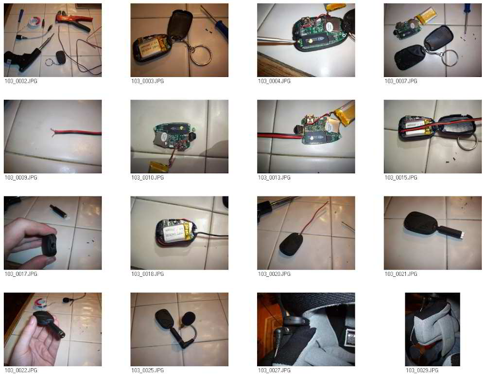
Helmet Cam Mod Project - Photos and Instructions
by Burns Hudson
Full Size Project Photos, 15MB - HelmetCamCameraMod.rar


Here is the guide I put together for adding an external audio
input. A video clip is on youtube
here:
http://www.youtube.com/watch?v=TVjmO1XIAQY
Supplies:
Soldering Iron (Soldering GUN will get too hot)
Solder
Small phillips screwdriver
808 Type 3 Keychain Micro Cam ~ eBay -
$8.32 delivered (http://shop.ebay.com/troyexporter/m.html?_nkw=keychain)
6 inches of speaker wire
Wire strippers (or knife/teeth)
1/8"
female audio plug ~ RadioShack - $2.16 each
Microphone ~ eBay -
$1.02 delivered (http://shop.ebay.com/toymodel99/m.html?_nkw=mini+microphone)
Beginner - 1 hour
Intermediate - 30 minutes
Pro - 15 minutes
Total cost of this project for me was $11.50 USD, including the
camera. $3.18 if you already have the camera.
Purpose: To modify the 808 cam so that it can be shoved
somewhere and have a remote audio feed. For me, it was to have a
helmet cam that can be mounted inside or outside of my helmet
and still be able to hear my voice clearly during my video blogs
-
http://www.youtube.com/djpyroaiken
● Step 1: 103_0002.JPG Gather supplies and start the iron
heating.
● Step 2: 103_0003.JPG Open up the camera - There are two small
screws located in on the back where the keychain loop connects.
● Step 3: 103_0004.JPG Locate the microphone. I am pointing to
it here with the screwdriver. The + side should be labled on the
circuit board.
● Step 4: 103_0007.JPG Take the circuit board completely out of
the casing. This is a type 3 camera, and one screw was near the
USB and the other near the mic. In my type 4, there is a screw
by the mic and one by the keychain loop.
● Step 5: 103_0009.JPG Strip and tin your wire. Tinning is the
process of applying solder to the wire so you don't need
anything but heat when attaching the wire to the board. This
helps to prevent keeping heat on the board as long to keep
things from getting too hot and frying.
● Step 6: 103_0010.JPG Detach the mic from the board. I
delicately bent mine back and forth until it snapped off, making
sure not to leave finger oils on the chips that could collect
dust.
● Step 7: 103_0013.JPG Trim the tinned wire to be about 2mm
long, then solder them where the mic was connected, making sure
to note which wire you connected to the + so that you can get
the phasing right when connecting the plug later on. (It will
still work fine if you get them mixed up, but if you are going
to do it, might as well do it right...)
● Step 8: 103_0015.JPG Figure out how far away you want the plug
to be from the end of the casing. Do a little mock-up to see if
everything fits.
● Step 9: 103_0017.JPG Cut out an opening in the back for the
wires, being sure to leave the screw holes untouched. I used a
Dremmel tool, but an Exacto-knife should do the job - this is
pretty soft plastic.
● Step 10: 103_0018.JPG Screw the board back in, and route the
wire. I ended up having to wire mine beside the battery so that
the case could still close without the need for glue.
● Step 11: 103_0020.JPG Put the case back on and screw it all
together. You now have a mouse-type thing.
● Step 12: 103_0021.JPG I got in-the-zone and forgot to take a
bunch of pictures here because I was in a hurry to finish before
dark, but attaching the audio connector should be
straight-forward. You want to make sure that the wire that was
NOT attached to the + is attached to the metal casing of the
plug (ground). If you have a stereo adapter, the + wire can
attach to either of the tabs that are sticking out, or you could
wire them together for mono. If you have a mono plug to begin
with, just attach and you are good to go. Be sure that in this
step, you have the black casing on the wire before you solder
anything. Otherwise, you will have to snip your connections and
redo this step.
Extra pic showing it off. 103_0022.JPG
Extra pic showing it off. 103_0025.JPG
Attached in helmet for nearly the EXACT view I have when riding.
103_0027.JPG
Mic wired up and wedged in the cushion to hang in front of my
mouth. 103_0029.JPG